Bare Metal C++ Register Access API
Contents
Introduction to memory-mapping
Note: This section is introductory material for those who are not yet familiar with the concept of memory-mapping. If you are already experienced with memory-mapping feel free to jump to the next section. Most likely you won’t miss anything new.
One of the most common ways of accessing peripherals from a CPU is memory-mapping. In short, this means that the address space of the CPU has some addresses that when accessed read/write peripheral’s registers. In order to access such peripherals from our code there are multiple strategies that could be used. This post will explore multiple alternatives and discuss their differences and fitness for their unique task.
As an example of memory-mapping we will have a look at a STM32F030 microcontroller. This is one of the simplest 32-bit ARM Cortex-M MCUs from ST Microelectronics. The architectural information we need is usually described in a Reference Manual document. This MCU contains an ARM Cortex-M0 core that interfaces via a Bus Matrix with multiple peripherals. The bus matrix provides access to multiple components of the MCU. Amongst them, we have the following:
- Internal
RAMmemory. - Internal
Flashmemory. - A connexion to an
AHB1bus, which bridges to anAPBbus.AHBis a bus designed by ARM part of theAMBAstandard. It is a de-facto standard for MCU buses in the ARM Cortex-M world and normally interfaces to high speed peripherals.APBis another bus also part of theAMBAstandard. It is a lower-speed bus dedicated to peripheral accesses, which normally do not require large throughput.
- A second
AHB2bus dedicated toGPIOports.- Notice how GPIO ports have a dedicated
AHB2bus. This makes sense if we would ever need to perform bitbanging of some protocol using direct GPIO control. In this case, having fast access to the GPIO ports is a clear advantage.
- Notice how GPIO ports have a dedicated
This architecture already hints that almost all peripherals are accessed via the APB bus. But, how do we access this bus from the CPU? In order to answer this question, we need to clarify how these buses work. When a bus is connected (interfaced) to another it has associated address ranges. If the address belongs to the target bus, then it is responsible of forwarding the request over this bus and reaching the peripheral located at the requested address.
For instance, accessing any address in the range of 0x48000000 and 0x48001800 will be forward the request through the AHB2 bus into the corresponding peripheral. The address range reserved for this bus is subdivided into address ranges reserved for peripherals. Therefore, to access GPIOA, which is mapped via the AHB2 bus, we can access any address between 0x48000000 and 0x48000400. The first address 0x48000000 address is also known as the base address of the peripheral, meaning that it is the first address that actually reaches the peripheral. Peripheral registers are often defined with respect to the base address, just providing an offset.
Now that we know the address range of the GPIO peripheral, we need to make sense of what each of the addresses in this range mean to the GPIOA peripheral. Thankfully this is quite a simple peripheral, so it will be easy to describe. This block of addresses is subdivided into registers. Each of the registers has a single associated address and size. The size of the register is normally native to the bus size of the CPU, which in this case is 32 bits.
The image below shows some of the registers of the GPIO peripheral.
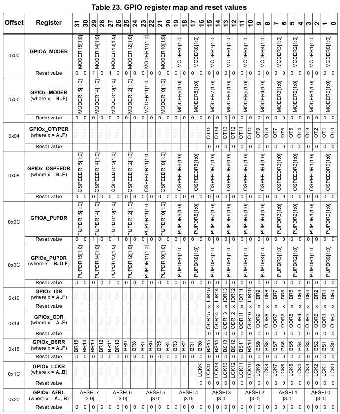
Therefore, an access to address 0x48000000 will modify the GPIOA_MODER register, used to change the operating mode of the GPIO. Each bit in this register has an associated meaning, also defined in the reference manual. Notice that some of these bits have a reset value different than 0. That is, when the peripheral is reset, this bit will be restored to this value.
Even though it is not shown in the previous picture, some bits in some registers might not be writable. For example, the GPIOA_IDR, which stands for Input Data Register, is a read-only register. The bits in this register cannot be written, as they would have no meaning (we cannot change an input value, after all).
Raw pointer access
The simplest way we can use to access a peripheral register is casting its address into a word pointer. By dereferencing this pointer we can then read or write the peripheral register. This can look something like the following:
| |
With this, we can write all 32 bits of the registers in a single go:
| |
Or read them also in a single access:
| |
Note that the use of reinterpret_cast in the previous examples can actually violate the strict aliasing rules. Therefore, care must be taken when using reinterpret_cast in this context to ensure that no other object is using this memory as a different type or the result will be undefined behavior. If you are interested in this topic, have a look at this post from Shafik Yaghmour.
Volatile access
There is a catch here, though. Registers often can change in HW without software interaction. This causes a potential issue with the compiler optimizer, as some accesses that might seem redundant to the compiler might actually be critical. For example, let’s say we need to wait until some HW FIFO is not full. We could write the following code:
| |
But the previous code has a fatal flaw. Given that nowhere in this code we change the address pointed by fifo_status, the compiler thinks it is fine to optimize the code in the following way:
| |
And with this, we can basically wait forever if the fifo was full. Since that is not what we wanted, as this register can change at any point in time, we need to mark the register access as volatile. One way of doing this would be:
| |
Now the compiler cannot optimize out the access in every iteration of the loop and the code is correct.
Advantages of the Raw pointer access:
- No infrastructure required other than knowing the addresses of registers and their bits.
- Easy to understand and comprehend.
- Register access is quite explicit.
Disadvantages of the raw pointer access:
- Manually writing the addresses can be very tiresome and errorprone.
- Accessing individual bits in the register can be complicated (requiring building masks and performing bitwise operations manually).
- Easy to forget the
volatilequalifier when declaring the pointer. Normally this isn’t such a problem for people that have been bitten byvolatileaccess before, but otherwise it is bound to happen. - There is no real type safety. We can write anything into any register, even if the peripherals don’t match.
- Basically no abstraction over the bare register concept. It is pretty close to writing assembly at this point.
- Difficult to unit test any code on non-target platforms. Mocking register accesses is not possible with this model.
Given all the drawbacks in the previous list, it seems clear that we should really look for a safer register access abstraction that tries to improve our concerns in the list of disadvantages. Let’s examine different approaches.
Getting help from unions and bitfields
For this section we will explore an alternative that ARM uses in its CMSIS libraries. This alternative consists on using bitfields to separate bit accesses and work with regsiters and bits in a more declarative way instead of procedural. So, for instance, let’s say that we have a register with the following fields:
| |
With this in mind, we could define a bitfield that represents this register:
| |
There are a couple of potential issues we should be aware of though:
- The bit order in a bitfield is
implementation defined, therefore, we need to know our compiler behavior to ensure that this code will behave as expected. This also means that this code is not portable. In most common compilers, the order of bits in the bitfield starts from the least significant bit first, so buiding witharm-none-eabi-gccorarmclangwill produce correct results for this particular case. - The types a bitfield can hold are limited to integral types and booleans. Compilers can augment the number of supported types, but yet again, this is
implementation definedand varies from compiler to compiler.
Now, assumming we are not concerned with the portability of this code, we can continue building on this solution. The next obvious thing we want to do is access the whole register in one go (without needing to read bits individually). To do so, maybe we could use a union type?
Turns out that, while in C using a union for type punning (accessing the bits of one object as another type) is valid, C++ disallows type punning using unions and explicitly makes it undefined behavior. At this point things are really getting hairy, aren’t they? Well, in practice, the ARM CMSIS libraries use unions for type punning in an extern "C" block (see here), so that should still be a valid alternative. Let’s see an example of how that would look like:
| |
Phew! Ok, we have arrived to a potentially decent solution, but how do we handle all the registers of a given peripheral? Probably the easiest is to make sure that they are part of a single structure of data. Let’s see an example:
| |
The only missing piece of the puzzle now is to put it all together and instantiate the registers. We could use reinterpret_cast as in the previous section:
| |
This is ok, but testing a uart driver may become a bit problematic, since the UART_BASE_ADDRESS will not be valid in unit tests. An easy solution to this is use some help from our friend the Linker Script.
| |
With this Linker Script we can now declare a static instance of our registers and map it to the correct section like:
| |
In a unit test, the .uart_regs output section will not be defined and therfore the input section .bss.uart_regs will form part of the output .bss section, making it just part of the program’s global unitinialized variables.
Now that we have achieved a viable solution using bitfields and unions let’s look at how it compares against the previous solution.
Advantages:
- It’s pretty great to be able to access bits without manipulating bit offsets.
- Volatile access is guaranteed by the struct definition. No need to worry about it when accessing the peripheral struct.
Drawbacks:
- Significant amount of non-portable
implementation-definedcode and potentially containingundefined behavior. In particular:- Bitfields are not portable because the bitfield order is
implementation defined. - Type punning via unions in C++ is undefined behavior. Actually, the only safe way to perform type punning in C++ is using
memcpy. - Limited type safety, as the bits in a bitfield can only contain integral types or booleans. Using other types is
implementation-definedas defined by the compiler you are using.
- Bitfields are not portable because the bitfield order is
- No control over what is writable and what is not. We cannot make certain bits in a bitfield read-only, but registers may have read-only bits in any given register.
- Little control over when the register is actually read/written. Bit access results in multiple read-writes, which may not be efficient or desired (What if we need to ensure all bits are modified in a single write?).
- No proper type safety, as bits are still integral types or booleans.
- Significant amount of non-portable
Let me demonstrate the register access drawback of wanting to do atomic register changes of multiple bits:
| |
Even in the second case, the situation is not ideal. Remember that the bitfields of the StatusRegister are volatile, so we are removing access optimization even to the temporary variable. Surely we could do better than that!
A safer API with strongly-typed fields
Well, given that we are using C++ and the language has largely evolved over primitive C types, there must be a better alternative to handle register accesses. So far all the code could be compiled in C as well and with no undefined behavior!. The following alternative will make used of functional programming features as well as object oriented features. Let’s start with creating an abstraction for a memory-mapped register:
| |
With this piece of code we can now use this class for any random 32-bit register. Notice that we take advantage of function pointers or closures in order to modify a register value and abstract the read-write-modify cycle. We don’t know how the register will be modified, as that should depends on the user code, but we know for sure that the register needs to be read first and later written after all modifications are done. That is a handy functional approach to this problem that we will keep using later.
However, you may ask what is the impact of using a closure as a function parameter, isn’t that too costly in runtime? Well, no! Given that the function is marked inline the compiler should be clever enough to figure it out. In fact you can see GCC does it here.
Now, for the next step, let’s create an abstraction for a specific register. We will use the same status register as defined in the previous section for the example.
| |
The StatusRegister class clearly states how to read, write or modify the register, using instances of type Fields to interact with these functions. Fields can either be instantiated with the value of the register or with the reset value of the register (default constructor).
The StatusRegister::Read method simply returns a Fields instance from which we can read the state of the regsiter.
In order to write the register, one can use StatusRegister::Write, which takes a closure that accepts a Fields as an argument. This Fields instance is default constructed, but the user can later override any fields they desire inside the closure.
Similarly, to modify a register, one can use StatusRegister::Modify. This function also takes a closure that takes 2 arguments. The first argument is a read-only Fields instance with the current contents of the register. The second argument is another Fields instance which one must populate with the settings desired to be written.
The Fields class also takes care of providing the correct encapsulation for the register fields. Read-only fields are not writable and special fields like clear-on-write can be safely handled with specific functions that cleraly state what they do.
Fields also provides a type-safe interface. For example, the Fields::state mehtod returns a State instance, something which was simply not possible with the previous version.
Let’s have a look at the tradeoffs of this new implementation.
- Advantages:
- Great control over field types and encapsulation.
- Functional approach to register writes and register modification actions.
- Register access is guaranteed to be volatile
- No extra overhead by unnecessary volatile qualifiers.
- Specific methods that clarify the operation of special registers like
clear-on-writeregisters. - No
undefined behaviordue to strict aliasing, as the bitfield is initialized from the register / read from the register using memcpy instead of an union type.
- Drawbacks:
- More code is needed to define the API, as it is not purely declarative as with the union example.
- Large overhead if optimization level is
-O0. Honestly, we should never be building code with-O0, so I personally don’t see this as an issue. - We are still keeping the bitfield, which is
implementation-defined. In most cases this is good enough as virtually all compilers use the same ordering for their fields. If desired, the bitfield could be replaced, as now it is only an implementation detail of theFieldsclass.
So we have achieved a pretty great solution, but it implies a very significant amount of code we need to write for every single register. This makes it rather errorprone so we must find a way to get around the new issue. The answer lays in code autogeneration. Given that the structure of the code is now known, it only needs to be specialized for each register. We will explore this in the next section.
Automating the job with SVD
Generating register code is something that we should be doing no matter what the chosen API is. But of course, to autogenerate such register API’s requires first having access to the peripherals and register definitions in a convenient format. In the case of ARM microcontrollers we are in luck.
ARM created a CMSIS System View Description (SVD) specification that although initially designed to be used with debuggers and other host programs, it is also quite useful for autogenerating peripheral access code. I won’t get into the details of how to build the code autogeneration program, but suffice it to say that you can find the SVD format specification here.
If you want to find the SVD files for common microcontrollers you can also refer to the CMSIS-Packs, a standardized way to deliver software components from ARM. SVD files will be contained inside the .pack files (which are essentially zip files).
Conclusion
In this post we have examined how to control memory-mapped peripherals of a CPU in an embedded context by designing an API that allows to control them in a type-safe, performant, free of undefined behavior and autogenerated manner. The result was an API that, although quite verbose, can be easily autogenerated and is safe and easy to use in the following regards:
- Explicit. It is very easy to identify when the register is being read/written.
- Volatile access is guaranteed by design.
- Volatile qualifiers are only applied to actual HW registers, even when we deal with the same data type in normal RAM, these accesses can be optimized by the compiler.
- Fields provide encapsulation.
- Fields provide type safety.
- Fields that have specific meaning (like
clear-on-write) can be adapted and included in the API clarifying the user’s expectation. - Zero overhead, as all code is seen by the compiler and can be reduced to a sequence of register accesses.
- No
undefined behaviororimplementation-defined behavior.
Note: In this post we have seen quite a few examples of undefined behavior and implementation-defined behavior. I probably even missed some, but please, do not dismiss the importance of undefined behavior. Code that seems to work today might not work tomorrow or even worse, code that seems to work today actually doesn’t in some subtle and perverse way. If possible, I would encourage you to look into other safer language alternatives like Rust, but of course this is not an option for everybody for multiple reasons (legacy code, language familiarity for the team, compiler support or other factors). That’s why I think as C++ developers we need to take an active role in the safety of the code we write and actively work with the best static/dynamic analysis tools at our disposal, as well as learning the intricacies of the language and being remarkably careful about safety.
Acknowledgements
The API presented here is inspired from the svd2rust project, which uses vendor SVD files to autogenerate rust code for register access known as peripheral access crates or PAC. The API defined in this article is, after all, an adapted version of the Rust code generated by the svd2rust project. Unfortunately, safety is not often the first concern when designing code in C++, but hopefully this article will inspire you to design safer API’s, free of the undefined behavior which so easily creeps into C++ or C code.
I personally hope Rust will become the next language for embedded development and I see a great wave of developers already pushing for more modern and safer programming practices. For now, many of us still live in C or C++ land, but that should not mean that we cannot benefit from some of the ideas around safety and modern development that are being brought into the embedded community but the new and vibrant embedded rust community.
Author Javier Alvarez
LastMod 2021-09-25