Bootloaders and ARM Cortex-M microcontrollers: Design
Contents
Welcome to the second entry of the Bootloader series! Today we are going to be discussing the design and basic architecture of the bootloader application.
As we talked about on the last post, we are not going to be using any libraries, other than the C++ standard library in order to maximize portability and performance and limit code bloat. This means that we will be writing our own Hardware Abstraction Layer for all the peripherals and core features of the bootloader.
In addition we need some startup code for the microcontroller. We have already discussed what startup code does and how it can be written to support C++ on a previous post named ARM Cortex-M Startup Code for C and C++. We are going to be using this code and adding ISR vectors to the NVIC table when we need to register a new ISR Handler.
In an arquitectural level we could establish the following hierarchy in terms of modules for our Bootloader.
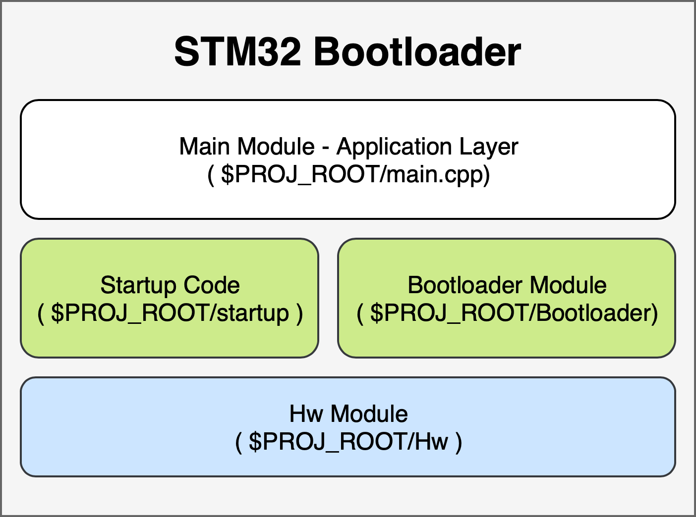
Module descriptions
Having already defined the main elements of the project, lets then define the function of each one of them:
Main Module
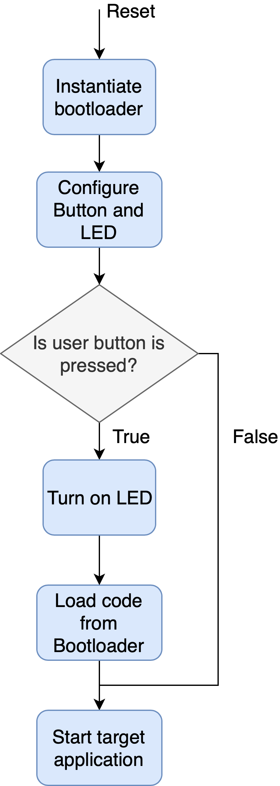
This forms the application layer. After the startup code is run, the main function gets called. Inside this function, we should check if the user button of the STM32F7 Discovery board is pressed. If it is pressed, we start the bootloader load process, waiting for commands from the remote loader and turns on the LED to signal bootloader mode. The flow diagram of this module is shown in the next figure.
Startup Code Module
There is not much to discuss regarding the startup code. Refer to the ARM Cortex-M startup code for C and C++ post if you want to understand how it is crafted.
Suffice to say that it takes care of initializing the following elements:
- Copying the data section from Flash to RAM.
- Filling with 0 the BSS section inside RAM.
- Calling constructors for all global static objects, which need to be initialized before they can be used inside the program.
- Specifying the Vectored Interrupt table. This contains function pointers to IRQ and Exception handlers, as well as the reset vector and the Initialization value for the Main Stack Pointer (MSP is located at register R13 in the armv7-m architecture).
- Initializing the floating point coprocessor.
Hardware Module
This module is probably the largest of the whole bootloader application. It provides abstractions for all hardware peripherals of the microcontroller. We will need the following drivers:
- GPIO
- SysTick
- RCC (Reset and clock control). This module controls clock gating for each peripheral (GPIO Banks and UART’s), as well as the reset properties of the microcontroller.
- SCB (System control block). We will use this to control the NVIC table relocation, as well as controlling access to features of the core Cortex-M7.
- Uart
- Flash
- SRAM
The following figure shows the relationships between classes, defining interfaces with gray blocks. Red blocks indicate resources specific to the STM32F7 microcontroller. The purple module contains base addresses for each peripheral and as such is very dependent on the specific microcontroller series and part. On the other hand, red peripherals are usually shared between processor families. In order to modularize them, red modules are template classes which are then instantiated into concrete classes in the orange module. Green modules control peripherals that belong to the core itself.
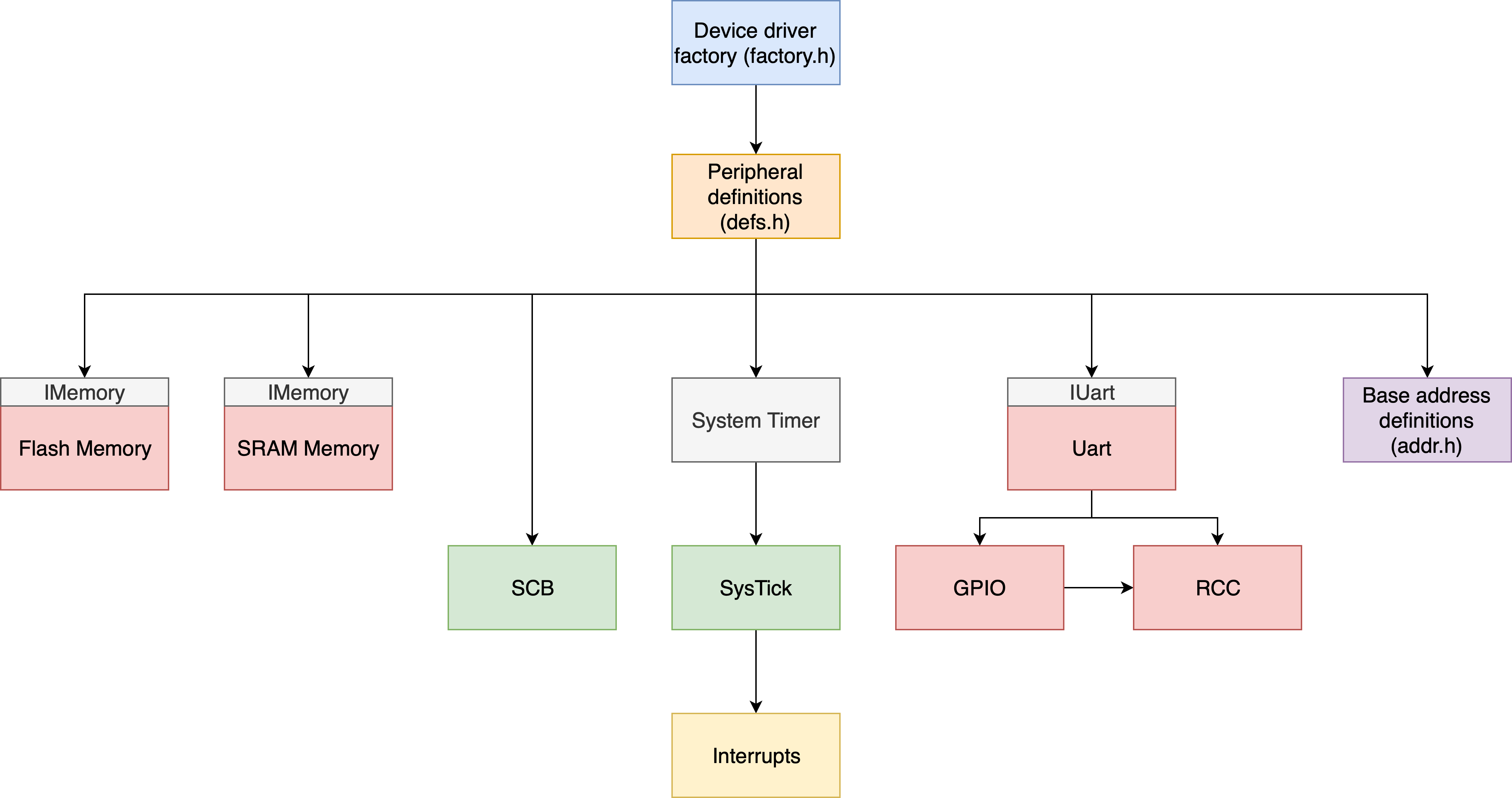
The System Timer is an abstraction of the SysTick driver. It is a system timer that counts milliseconds each time the timer overflows (at a rate of 1 kHz). This is currently the only module that requires interrupts in order to keep time. Given the simplicity of the bootloader no other interrupts are required.
It is critical to remember that any peripheral that gets initialized needs to be uninitialized when we jump to the target application. This is important for multiple reasons, but the most important is that interrupt vectors will be lost once the target application starts since the Interrupt Vector Table has been relocated and might not respond as you expect to interrupts from these peripherals.
Imagine that we forget to mask interrupts for the SysTick and disable the peripheral. Then, when we relocate the NVIC table we will have a different Interrupt Service Routine for the SysTick module. Moreover, if we have the default handler, we will be running into problems since most of the time it is just implemented as an infinite loop. In order to prevent unexpected behavior in the target application we must first disable the peripheral. Keep in mind that most applications will be written thinking that the reset vector is entered right after a POR, not from a bootloader, but registers might be initialized differently. In order to prevent problems we should just return all peripherals to their original state before jumping to the target application.
Since we would ideally like these modules to be as generic as possible, they will be template classes with parameters that include the base address of the peripheral and static configuration values. By doing this, we will have the hardware peripheral definition properly isolated from the drivers that handle these peripherals. This is done in a header file called defs.h that will include namespace aliases for the hardware peripherals of our STM32F746 microcontroller. An example of the contents of this file is shown below:
| |
By doing this and latter including this file to handle peripherals it is very easy to use a GPIO Pin, since it is already defined within the Hw namespace. Also, the addr.h file will contain the base addresses of all peripherals in constexpr declarations.
In order to get access to a UART we would also like to guarantee that only one UART object is instantiated for a given UART peripheral (let’s say for UART 1). The proper way to do this is by making constructors for these classes privates and having a Factory class that provides references to the singletons for each of the peripherals. This is done in the factory module.
Also, since we will create templates for all peripherals and instantiate each class for the given peripheral, we might want to inherit from a common class that provides a common interface for all peripherals of the same type. For instance, I could have a UART1 and UART6. Given this design, different classes are instantiated for each of them, since they have different base addresses. In order to have a common interface, we can inherit from IUart. Keep in mind that this also comes at the cost of having a virtual table for the methods that comprise the interface. It may be suitable for large peripherals, but maybe not so much for smaller peripherals (such as GPIO, where many different classes might be instantiated). If what you need is static polimorphism we could probably use CRTP. For this reason, GPIO is actually a class template which only contains static methods. No objects are ever created for them.
The last consideration for the HW module is that we need to remember to provide abstractions for access to SRAM and Flash memories. Since we want our bootloader to handle both indistinctly they will have a common interface with the following methods:
| |
Bootloader Module
The bootloader module is very straightforward. The functional requirements of this module are:
- Providing a custom protocol to handle communication with the remote. This is formed by a command parser and callback functions.
- Starting up the target application after the object code loader is done.
To accomplish these goals the bootloader will have two methods.
- The load method takes care of loading the target application code from the remote by parsing input commands and responding adequately. Once the host has finished the load process the method returns. Behind the scenes, this will use a separate loader module in order to separate command processing from the bootloader module itself.
- The boot method takes care of booting the target application. The first parameter is the address of the target application vectored interrupt table. This is needed in order to relocate the NVIC table and to get the reset vector.
Even though we will actually design the loader in a separate post, I will provide the requirements here.
- It needs to use a UART interface for the command parser.
- It will include some sort of command identification.
- It needs to be reliable in that it will check the integrity of received commands before blindly executing them.
- It needs to check address ranges and data received over the UART port to guarantee the integrity of the bootloader itself, making sure that it cannot be overwritten, bricking the device.
Defining partitioning space for Flash and SRAM memories
In order to be able to load code into the Flash and RAM memories we need to reserve some space for the target application code and some space for our bootloader. We will have the smallest Flash block for the bootloader code and the rest of blocks available to the target application (and therefore can be written by the bootloader). In terms of RAM, we have reserved 120 kB for the bootloader and 200 kB for the target application. This might seem a lot, but it makes sense given that we might add Ethernet bootloading in the future.
The memory layout is:
- Flash:
0x08000000to0x08007FFF: 32 kB block reserved for the bootloader.0x08008000to the end of flash: Available for the target application.
- SRAM:
0x20000000to0x20031FFF(200 kB): Available for the target application.0x20032000to0x20050000(120 kB): Reserved for the bootloader.
Author Javier Alvarez
LastMod 2019-05-31