On controlling GPIO speed
Contents
Most microcontrollers now include the options to select the GPIO speed for a certain pin inside a port. Many will announce this feature as GPIO max current control or slew-rate, but in the end they are talking about the same thing.
First of all, why would you ever need to control GPIO current? Wouldn’t it be great to leave this at the maximum level at all times? Well, it is usually not that simple, and more so as integrated circuits get larger clock frequencies. Let’s consider the following model of a push-pull GPIO in an STM32 microcontroller:
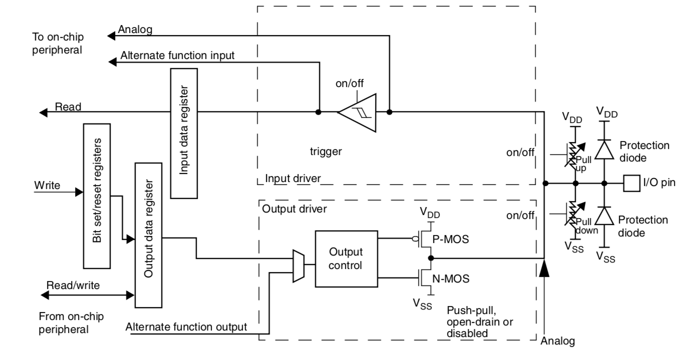
Controlling the output current of the GPIO is effectively controlling the maximum mosfet current when they are working on the active zone. If we consider the parasitic capacitance of the output trace and connected devices, the maximum current will affect the rise times on the trace. This is why this feature is sometimes called GPIO speed control or GPIO slew-rate control. But still, why is this an issue? We could always have the maximum current to satisfy fast commutation frequencies on every pin. These are the reasons why this isn’t usually a good strategy.
Signal integrity and EMC
Believe it or not, this could play a big role in electromagnetic compatibility. As I mentioned, increasing the available current for the GPIO means reducing rise and fall times. This, in turn, introduces larger frequencies on the trace, which could lead to signal integrity problems if the impedance of the trace is not correctly matched and terminated. Furthermore, it could not be destructive for the operation of the system, but at these frequencies PCB traces might start to act as antennas. It is important to keep in mind that auditing your device for CE Marking will perform EMC tests to your device to make sure that it complies with the current regulations.
I once worked on a device that was supposed to be a proof of concept (PoC) but was then repurposed after fabrication and needed to pass the CE Marking audit. The SD Card clock trace was radiating at 1.2 GHz, 10 dB over of the maximum allowed by the test. At this point you either reduce the GPIO speed (which is relatively inexpensive and straightforward) or you place a shielding around these lines to reduce the level of radiated energy (assuming that we want to keep the clock frequency constant). We, of course, went ahead with the option of reducing GPIO speed, since it simply was too costly to rework all units.
In general, it is a good practice to keep GPIO speed as low as possible (as long as it meets your functional requirements) to avoid situations like this in the future. So, anytime you need to set up a GPIO pin, remember to configure GPIO speed accordingly. It pays off later during the project, since discovering these bugs in the FW later in the project is always a painful and costly process.
Author Javier Alvarez
LastMod 2018-06-23